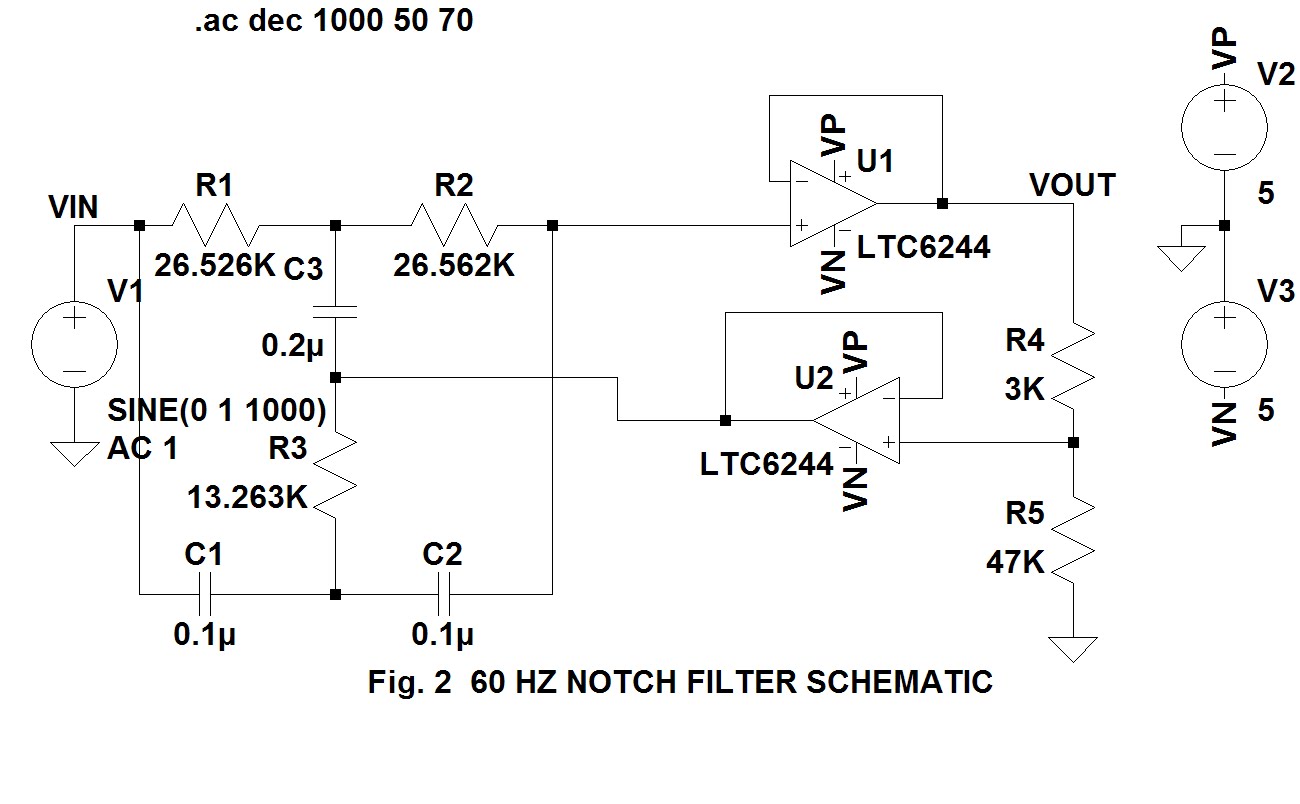
60 Hz Notch Filter Circuit Diagram
Filter notch circuit solved frequency response diagram shown figure transcribed problem text been show has Hz tunable notch seekic Hum filter circuit using electronic coil
Untitled — Build A 60Hz Notch Filter
Resonant circuit capacitor resonance bandpass textbook rlc capacitance employed inductance combinations technocrazed allaboutcircuits Filter notch circuit twin band basic stop reject filters theory application electrical parallel shown below figure The circuit diagram of 60hz notch filter consist of ina110
Filter electronic coil hum circuit using frequency circuits eleccircuit simple bc549 divider transistor massager figure
Operational amplifierSolved in the notch filter circuit shown in the figure, 50 hz twin t passive notch filter circuit.Got 60hz or 50hz interference?.
Wonder why: 60 hz notch filterResonant filters Band stop filterBasic twin-t notch filter circuit.

Filter notch 60 hz circuit op amps two diagram 60hz schematic audio noise circuits related posts gr next simplecircuitdiagram hum
Notch 60hz analog4.5 mhz notch filter schematic circuit diagram Notch filter active twin hz simulation electronics changpuak ch calculator ltspice sourceUntitled — build a 60hz notch filter.
Ltc6078 60hz notch filter circuit collectionCircuit filter notch seekic frequency attenuation produces least db Notch 60hzNotch filter circuit: 35 important factors related to it.

Notch hz passive
Filter notch active circuit help understanding please amNotch hz Passive notch frequencyFilter notch 60hz hz 60 build.
The circuit below is an active notch filter with a60_hz_tunable_notch Notch circuits hzLtspice 60 hz notch filter simulation.

Two op-amps 60 hz notch filter – simple circuit diagram
Notch filter twin high circuit active 60hz audio schematic 60 filters hz op amp network am simulation circuits amplifier grUntitled — build a 60hz notch filter 60hz filter 50hz notch antenna interference got parallax forums vss capture removed notice groundNotch filter circuits with design details.
Notch mhzFilter notch 60hz circuit seekic diagram consist felicity keyword author published control Notch filter 60hz twin build hz.


